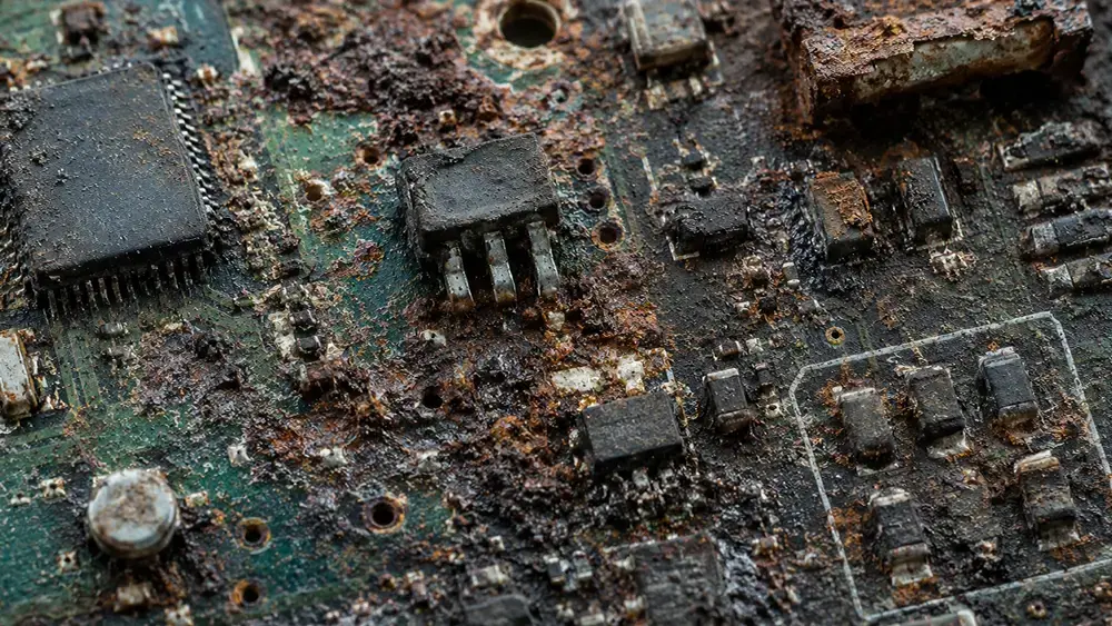
How to Prevent Corrosion in Electronics and PCBs
Overview & Key Takeaways Moisture and contamination are the primary drivers: Humidity, condensation, salts, ionic residues, and airborne contaminants create conductive pathways..
How Is Parylene N Different From Other Parylene Variants?
Overview & Key Takeaways Parylene N is the base polymer in the Parylene family of conformal coatings. Unlike other variants, it contains no halogens or additional chemical groups...
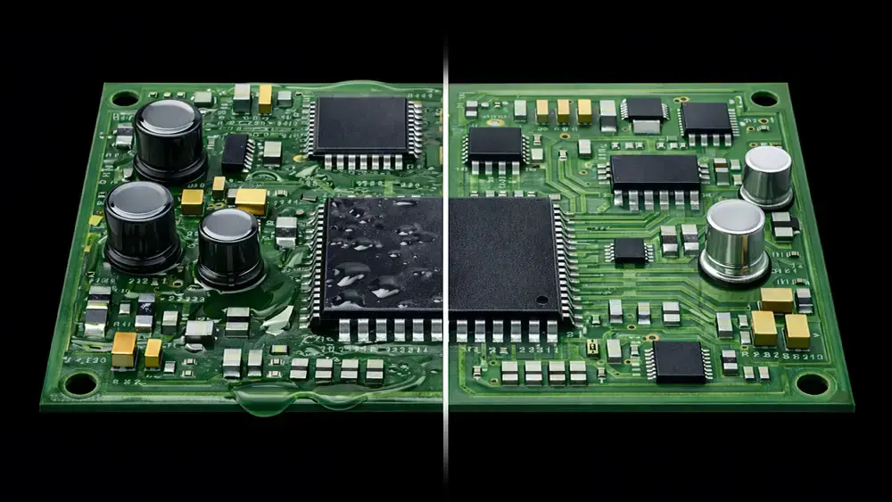
Parylene vs Liquid Coatings: An Engineer’s Selection Guide
Overview & Key Takeaways This guide provides engineers with a practical, side-by-side comparison of Parylene coatings vs. traditional liquid conformal coatings to support informed..
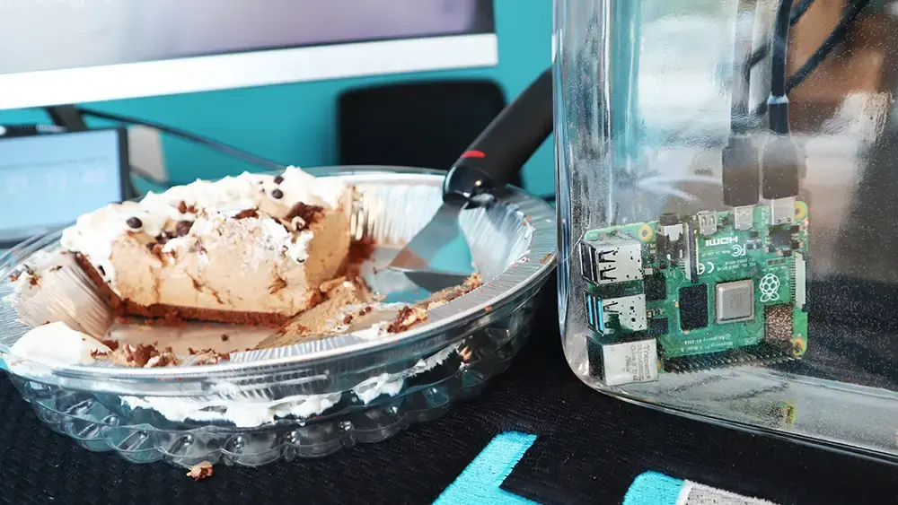
HZO Celebrates Pi Day 2025
In honor of Pi Day 2025, the HZO Team in Morrisville, North Carolina, headquarters honored our beloved Raspberry Pi computer that has been running and displaying our demo video -..

MIL-I-46058C: Definitive Guide to Military Standards for PCBAs
Reliability is a top priority in defense and aerospace electronics in harsh, unforgiving environments. The MIL-I-46058C standard is a guideline for conformal coating materials..

Polymer Glass Transition Temperature - Material Properties, Impact
Polymer glass transition temperature (Tg) refers to the temperature at which an amorphous polymer transitions from a glassy, rigid state to a rubbery, flexible state...
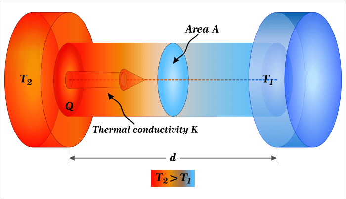
What is Thermal Conductivity? Explanation, Measurement, Uses
Thermal conductivity is a fundamental concept in heat transfer and is crucial in multiple industries and scientific disciplines. It refers to the ability of a material to conduct..

What is the Index of Refraction? Measurement, Definition & More
Understanding how light travels through different mediums is essential in optics. One invaluable optical property is the index of refraction. This measurement quantifies how much..
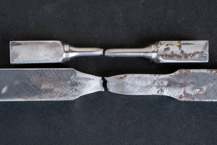
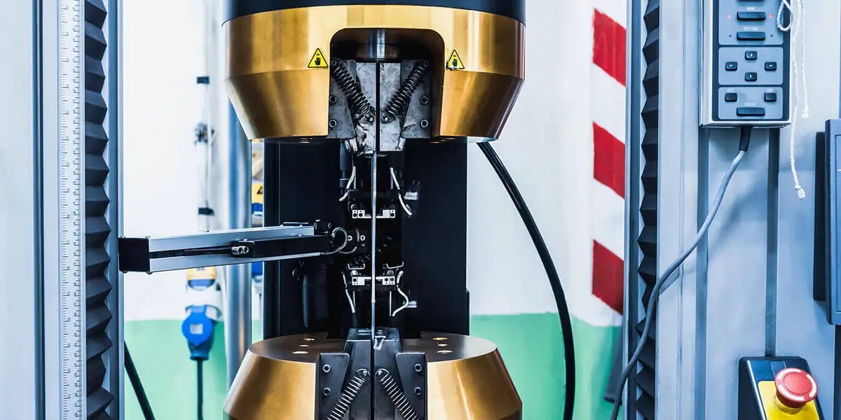
Tensile Strength at Yield - Testing, Standards, Specs, Material
The ability to accurately predict the behavior of coating materials under tension is crucial in ensuring the integrity and reliability of electronic components. This includes..
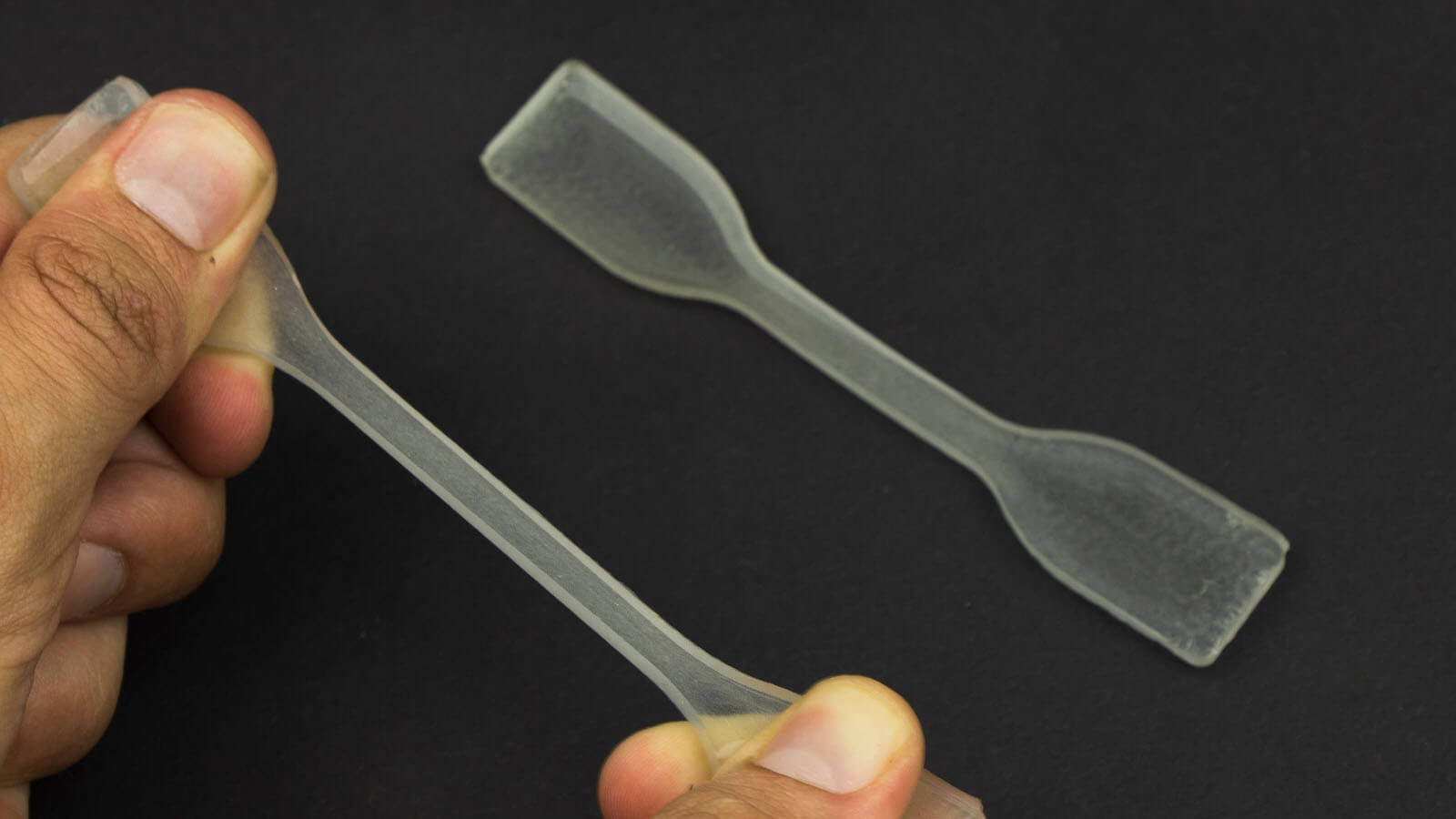
Elongation at Break - Definition, Testing, Material Selection
Elongation at break is a key mechanical property that measures the deformation capacity of a material before it eventually snaps or breaks, providing insights into the material's..
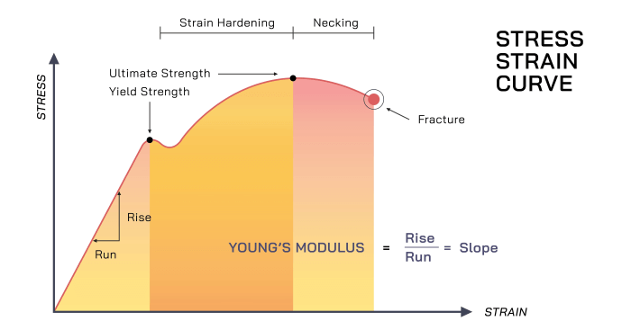
Young's Modulus of Polymers - Measurement, Calculation
Young's Modulus is an important property, allowing engineers to select coating materials based on their desired stiffness. Understanding and manipulating the elastic Modulus of..
Water Vapor Transmission Rate - Standards, Testing, Material
In the world of electronics, moisture control is of utmost importance. High water vapor transmission rate (WVTR) can pose significant risks to sensitive electronic devices. When..

Transparent Polymers - Applications, Material Selection
Transparent polymers offer optical clarity and the ability to transmit light. With various applications across various industries, these polymers have gained popularity for their..

Biocompatible Coatings - Coating Techniques, Applications, More
Biocompatible coatings seamlessly integrate with the human body, offering benefits through their ability to promote healing and prevent adverse reactions. They can improve patient..
Dissipation Factor - Definition, Measurement, Variables
Dielectric materials are crucial in various industries and applications, serving as insulators, substrates, or capacitors. One important characteristic often evaluated in..

Volume Resistivity - Definition, Measurement, Product Design
Whether designing circuit boards or protecting electrical components, knowledge of the volume resistivity of coating materials plays a pivotal role in creating efficient and..
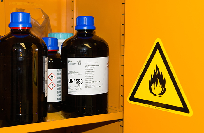
UL94 Coating Material - Testing Method, Material Selection
Fire safety compliance is an indispensable aspect across various industries. One crucial benchmark in fire safety compliance is UL94, a widely recognized standard for flammability..
Elongation Yield: Overview, Unit of Measure, Data and Testing
Elongation yield refers to the maximum amount of deformation a material can undergo before it experiences a permanent change in shape or size. This property is fundamental in..

Difference Between Water Resistant, Repellent, & Proof
If you're looking for the highest quality protection from the inside out, contact HZO today. We all see references to waterproof, water-resistant, and water-repellant devices..

IP Ratings Decoded: IP57, IPX7, IPX5 Explained
Download the IP Checklist Download Checklist Download HZO's Ingress Protection (IP) Checklist Your shiny new smartwatch claims to be IP57 waterproof, your new phone claims to be..
Dielectric Constant of Insulator Materials: Formula, Table of Values
Depending on their formulated ingredients and molecular structures, thin film coatings may be electrically conductive, insulative, or semiconductive. Insulative coatings serve..

What is the Dielectric Strength Formula? Testing, Table of Values
Although thin film coatings serve many purposes, providing dielectric isolation and electrical insulation is one of the essential functions. Dielectric strength is an important..

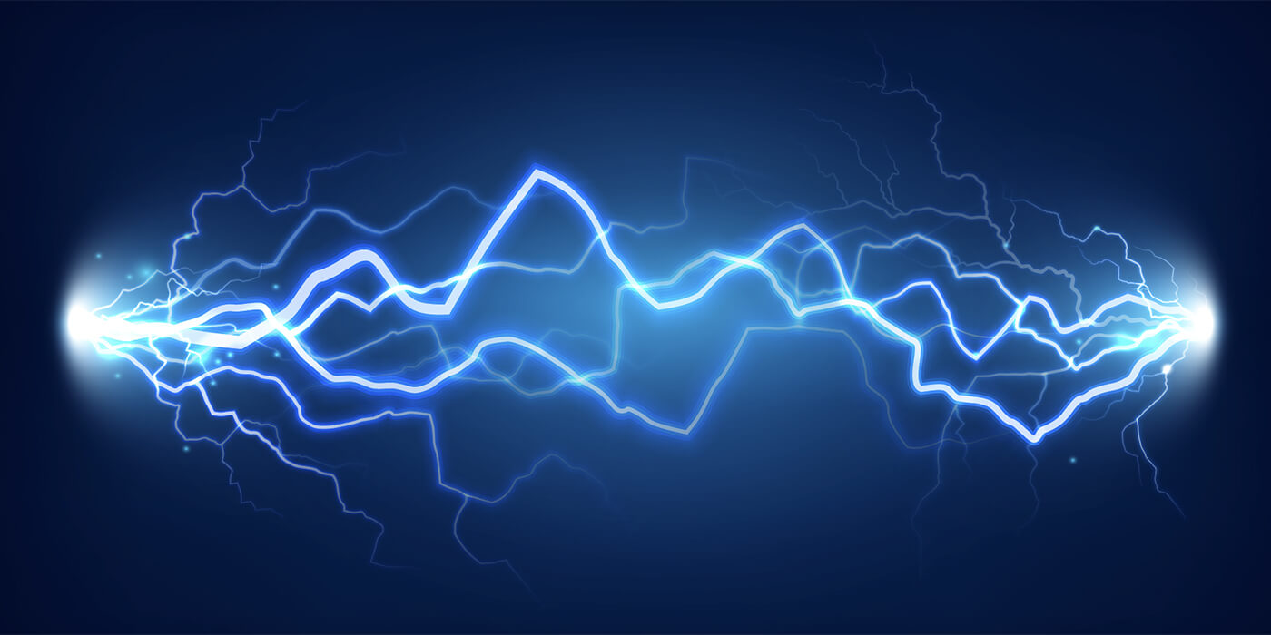
Arc Resistance - Concepts and Testing Explained
Insulating materials such as Teflon, plastic, rubber, ceramic, or glass ensure products function properly and safely. However, no insulator is perfect. These materials still..

NEMA vs IP Ratings Explained
Once upon a time, computers only sat perched on desktops, but that is no longer the case. Deployed in harsh industrial, medical, automotive, and consumer household environments,..

Solving Weather & Water Challenges For Smart Farms
It’s a Small World, After All The world’s population is projected to reach 8.5 billion by 2030, an unprecedented increase approaching fast. This looming surge will compound our..

Designing a Waterproof Product With IP Ratings
The Big Picture: Manufacturers determine IP ratings, not an impartial group. Although these rating systems are useful for comparison purposes, they are not the panacea for rating..
Don't Be Left in the Dark: Brief History of Light Emission Devices
One of the best things about working for a company like HZO is the opportunity to be exposed to an extremely wide variety of technologies (apart from our own). Our seasoned..

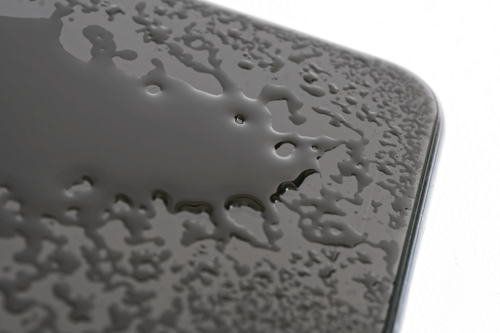
Hydrophilic vs Hydrophobic: What's The Difference?
Hydrophilic vs. Hydrophobic Today’s technical terminology can be dizzying. On an average day here at HZO you hear people throw around words like nanotechnology and vapor..